The following sections explain the details of the control algorithms. They are easier to understand if you have the hydraulic schema and an overview of the control system at hand (PDF or TAPPS2).
Wood-fired Furnace and special Features
The wood-fired furnace is not controlled actively by the controller but rather by the amount of wood set on fire. The purpose of the control system is to efficiently transfer as much of the thermal energy generated by the furnace into the buffer as possible. This is done by feeding cool water from the buffer into the furnace circuit and hot water from this circuit into the buffer at the same time using a mixer.
The furnace and connecting lines circulate hot water so that the built-in heat exchanger is operated at high temperature. This is to avoid soot agglomeration on its surface which would hamper heat transfer from the smoke gas to the water in the heat exchanger thus diminishing its efficiency.
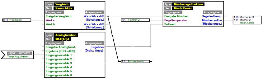
The furnace circuit is activated if the Comparison KaminAktiv detects a temperature rise in the heat exchanger S11 above a fixed threshold of 60°C. This activates the circulation pump A6 in the circuit with constant pump speed and the Mixer controller MischKamin. In the initial phase of operation the water in the circuit is circulated in a closed loop (mixer closed) and heated by the heat exchanger. To feed the water into the buffer at least the temperature THeizungsunterstützung has to be reached in the circuit. The Analog function MAX(An)4 thereby implies a lower limit on the target temperature in the circuit of about 70°C and then sets the resulting temperature as an input for the Mixer controller MischKamin. This controller function regulates the water temperature fed to the heat exchanger by opening or closing the mixer A10/A11. It opens the mixer if the temperature within the circuit rises thus mixing cool water from the buffer into the circuit and feeding hot water into the buffer. The thermal energy meter S14/S15 measures the thermal power and energy transferred from the furnace to the buffer. In contrast to classic mixer opertion e.g. in the floor heating circuit the mixer here operates in an inverted mode because here the furnace acts as the heat source and the buffer acts as the heat sink.
The temperature required to support the floor heating system using other heat sources has already been referenced several times in this documentation. It is calculated by the controller using the following algorithm:
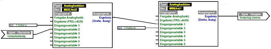
According to this the THeizungsunterstützung=Min(Tbuffer-mid,Max(Tbuffer-bottom,Tfloor-heating-flow-target)) which has the following effect on the control algorithms:
- Tbuffer-bottom is the lowest temperature in the buffer because of the natural layering of the temperature zones within the buffer. This is the lowest possible temperature to support the system because otherwise no heat transfer into the buffer is possible.
- Tfloor-heating-flow-target is the current target temperature of the flow in the floor heating circuit. It is calculated by the heating circuit controller module of the UVR1611 based on the outside temperature. This temperature also acts as a lower limit on the buffer feed temperature because water with lower temperature cannot directly be consumed by the floor heating system.
- The larger of both values then is the required buffer feed temperature.
- An unfavorable situation occurs when the buffer is empty and the collected solar power is too low to reach Tfloor-heating-flow-target in the feed line to the buffer. In this case no heat would be transferred into the buffer even if the collected solar power would be sufficient to store at least a little bit of thermal energy into the buffer. The algorithm therefore sets Tbuffer-mid as a lower limit so that at least the lower part of the buffer can be used to store some thermal energy even if the temperature is too low to directly use it for the floor heating system. So at least some thermal energy is collected and stored and less energy later is needed to heat this water up to the temperature required by the floor heating system using the gas-fired furnace.
The control systems for the gas-fired furnace, the solar thermal system and the wood-fired furnace have been modelled independently and the UVR1611 controller runs them concurrently. However, the individual control subsystems are indirectly coupled by the temperatures and water flow paths of the installation. Some controller inputs or outputs are used multiple times in different parts of the control algorithms as control factors or command variables. In practice some situations occur where this indirect coupling of the subsystems requires some optimization:
- If the wood-fired furnace is fired it produces warm air to directly heat the rooms and also feeds hot water into the buffer. The gas-fired furnace then normally can be stopped.
- The same applies for the solar thermal system which collects enough thermal energy for the floor heating system as long as the sun shines. In addition large south-facing windows allow sun radiation to directly heat the rooms. The gas-fired furnace is not needed in this case, but might still be needed for tap water heating.
- If the outside temperature is extremely low the gas-fired furnace is required to support the solar thermal system because the collected thermal energy is not sufficient most of the time to fulfill the demand of the floor heating system.
- The same applies to the wood-fired furnace. Its average power is not sufficient to generate enough thermal energy for heating if outside temperatures are extremely low, at least if wood is not supplied continously. This is also due to the fact that the wood-fired furnace generates hot water which collects at the top of the buffer. From this zone it is accessible for the on-demand tap water heating but not for the floor heating system because of the hydraulic schema.
- Rather cool outside temperatures in spring or fall cause a rather high demand of thermal energy for the floor heating system. If the thermal energy collected by the solar thermal system is barely enough to supply the floor heating without any excess energy being stored in the buffer, a short interruption in solar radiation by a cloud will immediately cause a drop of the flow temperature in the floor heating circuit. This will trigger the gas-fired furnace and lead to a start/stop of the furnace with every single cloud.
- On the other hand a continous operation of the gas-fired furnace under simulat conditions will immediately be interrupted by even a short period of sunshine.
To handle these special cases the individual control algorithms for the subsystems have to be connected using additional logic circuits which control the activation of the floor heating system and the gas-fired furnace. These circuits may stop the operation of the gas-fired furnace under certain circumstances but will not influence the operation of the solar thermal system or the wood-fired furnace. This is because we want to collect as much thermal energy as possible and store it in the buffer, and we cannot really control the operation of the wood-fired furnace anyway because wood is fed to the furnace manually.
Whereas the first few bullets can be handled by simple comparisons the sun-cloud problem requires an analysis of the duty cycle of the solar thermal system because we want to run the gas-fired furnace on a cloudy day continously, and we want to switch it off on a sunny day even if there are a few clouds.
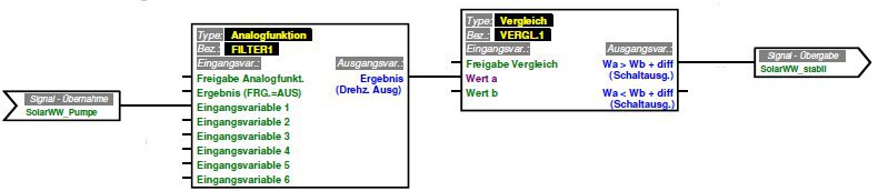
In order to analyze the duty factor we calculate the average speed of the pump on the secondary solar circuit using an Analog function FILTER1. The pump speed setting output of the corresponding PID controller will be 0 if the solar thermal system is switched off and will be larger than 0 otherwise. Its temporal average therefore is an indicator for the total thermal energy collected in the chosen time interval (20 - 30 min). We compare the averaged pump speed with a fixed threshold value using Comparison VERGL1. If it is larger than the threshold we assume a sunny day with just a few clouds, if it is less we assume a cloudy day with just a few short periods of sunshine. We carry out this computation for the floor heating mode of opertaion of the solar thermal system and for the tap water heating mode separately.
It might be interesting to note that the averaging function doesn't just cosider the on/off-times but also takes into account the average solar power (via the speed setting of the pump). To just average a digital (on/off) signal is not possible with the filter function module of the UVR1611 due to a confirmed bug in the firmware of the controller (as of 21.12.12).
The other special cases mentioned above will just require a few logic functions:
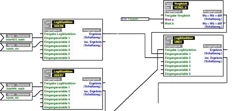
- The Comparison VERGL5 compares the outside temperature with a fixed threshold and so decides if we currently are in "winter" mode. In this case the solar thermal system is operated in floor heating mode only and tap water heating via the solar thermal system is blocked. Additionally the floor heating system and the gas-fired furnace will never be blocked in this case even if the solar heating system detects sunshine or the wood-fired furnace is fired because both of them will not continously produce enough thermal energy to supply the floor heating system under normal circumstances.
- The Logic function ODER7 combines the result of the duty factor calculation for the solar thermal energy collection with the state of the wood-fired furnace. Its inverse output blocks the DHW demand WW_ANF thus stopping the tap water heating via the gas-fired furnace in case a stable tap water heating via the solar thermal system is possible or the wood-fired furnace is in operation.
- The same functionality is implemented by the Logic function ODER8 for the floor heating system.
- Logic function UND1 combines the output of ODER8 with the condition "not-winter" and blocks the heating demand module. Via an activation of UND1 the heating demand module is also blocked in case of a concurrent DHW demand is active thus unambigously having active only one demand at a time.