The following sections explain the details of the control algorithms. They are easier to understand if you have the hydraulic schema and an overview of the control system at hand (PDF or TAPPS2).
Control of the Heating System and on-demand Tap Water Heating
Our floor heating system is controlled by the UVR1611 function module Heating circuit controller FBHEIZ. Here the flow temperature is regulated using a mixer A8/A9 which feeds warm water into the floor heating circuit thus keeping the flow temperature at its desired level. Source of thermal energy preferrably is the buffer or alternatively the gas-fired furnace in case the buffer is empty. The Heating circuit controller FBHEIZ also measures the outside temperature S 12 to calculate the required flow temperature via the built-in and properly parameterized heat curve. Additionally this controller switches the floor heating circulation pump A 7 as required. This pump autonomously adapts its pump speed.
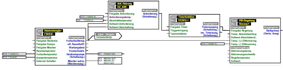
The function module Heating demand HZ_ANF checks if the floor heating system can be fed with thermal energy from the buffer (S 6) or if the activation of the gas-fired furnace is required. It does so by comparing the actual flow temperature S 10 with its target value calculated by the Heating circuit controller FBHEIZ. It requests the activation of the gas-fired furnace if the flow temperature drops significantly below its target value meaning that the demand of thermal energy can no longer be supplied by the buffer. As trigger temperature to stop the gas-fired furnace the temperature in the middle of the buffer S 6 is used because thermal energy for the floor heating system is drawn from this buffer zone. Additionally a small underflow is allowed in order to increase the overall system stability and to compensate for small fluctuations in the temperature caused by water currents within the buffer which shall not lead to an immediate start of the gas-fired furnace. By combining this underflow and the temperature set/trigger points it is possible to empty the buffer even a few degrees below the target flow temperature before starting the gas-fired furnace.
Power control of the gas-fired furnace is done via a 0-10V voltage signal A 15 created by the PID controller Brenner1. This controller is operated in difference value control mode with the calculated flow temperature as the upper and the actual flow temperature S 10 as the lower value of the difference. The actual flow temperature S 10 here acts as the control factor, the desired difference to the target is fixed to small positive value (approx. 0.5°C). This will control the output power of the gas-fired furnace A 15 so that the actual flow temperature S 10 is slightly lower than the calculated target value. The heat curve in the Heating circuit controller FBHEIZ is shifted to a higher set temperature by this amount so that eventually the floor heating system is operated with the correct flow temperature.
This trick is required to compensate for the design of the hydraulic schema. The flow temperature in the floor heating circuit is influenced by the mixer A8/A9 which is controlled by the Heating circuit controller FBHEIZ. It is also influenced the the temperature S 9 in the feed line which in turn is a result of the currently set furnace power controlled by the PID controller Brenner1 in case the gas-fired furnace is active. This means that two independent control variables act upon the same control factor S 10 which may lead to unexpected behavior of the controller. By setting different target values for both controllers we achieve a prioritization resulting in this behavior:
- If the buffer can supply enough thermal energy to fulfill the demand of the floor heating system the gas-fired furnace is stopped. The floor heating system is supplied with thermal energy from the buffer. The Heating circuit controller FBHEIZ keeps the flow temperature S 10 constant by controlling the mixer A8/A9.
- Because thermal energy is drawn from the buffer the temperature of the water fed from the buffer into the floor heating via the mixer will decrease over time. This will be compensated by the Heating circuit controller FBHEIZ which will open the mixer A8/A9 to keep the flow temperature S 10 at its calculated level.
- If the flow temperature S 10 can no longer be held at the calculated level by supplying the floor heating from the buffer alone, the Heating demand HZ_ANF will activate the PID controller Brenner1 and thereby the gas-fired furnace A 15. The mixer A8/A9 already is fully open at this point.
- The PID controller Brenner1 increases the output power of the gas-fired furnace A 15 to a level high enough to bring the flow temperature S 10 up to (almost) its calculated target value. However it will stay below this target value by about 0.5°C according to the parameter settings explained above. This will keep the Heating circuit controller FBHEIZ from closing the mixer A8/A9 so that the mixer will stay fully open. This means that the gas-fired furnace will produce exactly the amount of thermal energy used by the floor heating system at any point in time.
- In case the PID controller Brenner1 tries to lower the power of the gas-fired furnace below its technical limit and still more thermal energy is produced than currently demanded by the floor heating the flow temperature S 10 will rise. If its value reaches the calculated target temperature (i.e. increased by 0.5°C) the Heating circuit controller FBHEIZ will start to close mixer A8/A9 thus keeping the flow temperature at its level.
- In the hydraulic schema the gas-fired furnace, the buffer and the floor heating are connected in parallel so in this case the excess thermal energy is automatically fed into the buffer for later use. The gas-fired furnace is stopped only if enough thermal energy has been stored in the buffer to run the floor heating with heat from the buffer (S 6). So the duty cycle of the gas-fired furnace can be optimized and frequent starts/stops are prevented.
The Timer VERZG1 hereby delays the activation of the PID controller Brenner1 a few minutes whereas the activation signal is forwarded to the Analog function Max(An)3 in parallel. This has the effect that the gas-fired furnace is started with its minimum power setting and its power is adapted by the PID controller Brenner1 a few minutes later. This improves stability of the control because immediately after starting the gas-fired furnace all the lines are filled with cold water which would cause the PID controller Brenner1 to increase the furnace power way too high and induce unwanted oscillations in the control loop.
For tap water heating we use an autonomous system which heats cold tap water on demand to the desired temperature via a water heat exchanger. The required thermal energy is taken from the topmost thermal layer in the buffer which is held at the desired tap water temperature at all times. The supply of warm water to the top of the buffer occurs via the solar thermal system if sufficient solar power is available. Otherwise the gas-fired furnace is used to heat the topmost thermal layer in the buffer.
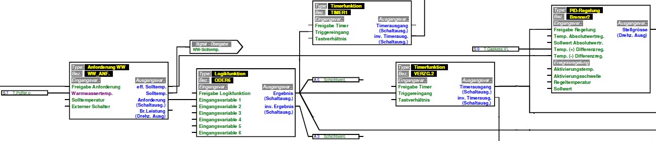
The algorithm to start and power-control the gas-fired furnace is simular to the one used in the floor heating mode. In this case however the target temperature is set to a fixed value and independent of the outside temperature. The DHW demand WW_ANF module checks if the temperature at the top of the buffer (S 7) is sufficient for tap water heating. If this is not the case the gas fired-furnace A 15 is started and via the PID controller Brenner2 set to the power level required to heat the water in its output line S 9 to the effective target temperature for tap water heating. In other words the water is not heated to a higher temperature than necessary.
The water fed from the buffer to the gas-fired furnace in this phase is taken from the zone below the topmost zone in the buffer. This is accomplished by a switch of the water flow paths in the system via the valves A 3 and A 5. So only the minimum required amount of water needs to be circulated and heated. The water is the fed into the buffer at its top so that the termal layers in the buffer will shift downward over time. The shift of the thermal layers within the buffer causes the water supplied to the furnace to get warmer during the process so the power of the gas-fired furnace can be reduced. The valves are operated using thermal drives so the switching process itself takes a couple of minutes. Delay timers within the control algorithms are used to take this into account. Summing up the individual moduls express the following overall behavior:
- The DHW demand WW_ANF activates the tap water heating mode of the system if the temperature in the topmost thermal layer in the buffer (S 7) drops below the required temperature. However, the activation of this mode of operation may be suppressed in certain situations, see below.
- The Logic function ODER6 takes the activation signal and generates the corresponding outputs for the valves A3 and A5. The signal is also set as input for the Analog function Max(An)3 which then starts the gas-fired furnace at a minimum output power level.
- The Timer VERZG2 delays the activation of the PID controller Brenner2 until the thermal drives have set the correct valve positions. At the same time a signal is sent to the Analog function Max(An)3 and so generates a lower limit for the output power setting of the gas-fired furnace. In this way the range of the PID controller Brenner2 can be extended below the technical lower limit of the furnace thus preventing the unnecessary starts/stops of the furnace. This also improves the responsiveness of the control when operating the furnace at low power levels. In addition the Timer VERZG2 via Logic function UND1 blocks a possible concurrent request for the gas-fired furnace by the floor heating system. This is required to block the PID controller Brenner1 used for the floor heating power control which otherwise would set the gas-fired furnace to the maximum power level when operating in tap water mode because due to the different settings of the valves the paths of water flowing in the system has been changed and a closed control loop for the PID controller Brenner1 no longer exists.
- The Timer TIMER1 will generate from the original request signal a single pulse with a duration of several minutes. This pulse will stop the floor heating circulation pump A 7 and close the mixer A8/A9 during the startup phase and power ramp-up of the gas-fired furnace. This prevents the flow of hot water into the floor heating system because the Heating circuit controller FBHEIZ would not be able to close the mixer A8/A9 fast enough. When Timer TIMER1 falls back to its normal state the Heating circuit controller FBHEIZ is activated again and will start to slowly open the now closed mixer. The floor heating system then is supplied out of the buffer if enough thermal energy is available from there. Timer TIMER1 also triggers at the falling edge of its input signal. This also will stop the floor heating system for a few minutes and prevent hot water still present in the lines from a completed tap water cycle to flow into the floor heating circuit.
- The PID controller Brenner2 sets the right power level for the gas-fired furnace during tap water heating mode. It is activated with a short delay to allow the thermal drives to switch the paths of water flow via the valves A3 and A5.
- The Analog function Max(An)3 finally collects the outputs of the PID controllers and the digital switch signals. The digital switch signals become active before the PID controllers and will cause the gas-fired furnace to start with power set to a minimum. If the furnace is already active at this time they will prevent an interruption of furnace operation if some of the signals get interrupted for a short period while switching from floor heating mode to tap water heating mode and vice versa. This will reduce the overall number of starts/stops of the furnace and keep the furnace running for longer periods of time. This way duty cycles with a length of several days are possible for the gas-fired furnace.