The following sections explain the details of the control algorithms. They are easier to understand if you have the hydraulic schema and an overview of the control system at hand (PDF or TAPPS2).
Control of the Solar Thermal System
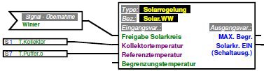
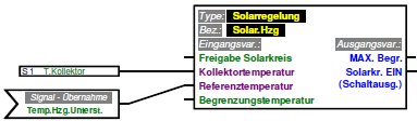
The activation of the solar thermal system is controlled by the UVR1611 via the function Solar control. We need two instances of this module because we use the solarthermal system for heating of tap water as well as a supply for the floor heating system, SolarWW and SolarHzg. Both will check whether the temperature of the flat panel collector S 1 is larger than the corresponding reference temperature (S 7 or THeizungsunterstützung).
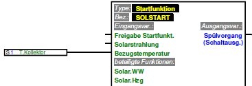
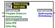
In addition we use the Start function SOLSTART in order to start the solar thermal system as early as possible. We do not have a solar radiation sensor in our installation. Priorization of both controls is via the Solar priority SOLVORR function of the UVR1611 so that at each point in time only one of the solar controls is active. We prioritize the tap water heating mode of operation in favor of the floor heating mode of operation provided the generated solar power is sufficient.
The conditions mentioned above will activate the solar thermal system if feeding thermal energy from the solar system into teh buffer is possible. In addition they control the mode of operation and tune it to tap water heating or floor heating. However, it doesn't make sense to operate the system in tap water heating at all times. If there is enough warm water stored in the topmost thermal layer within the buffer for on-demand tap water heating the production of even more water at this relatively high temperature level would not make sense. In this case available solar energy should be fed into the floor heating system even because otherwise the gas-fired furnace would have to be activated to drive the floor heating system even if enough solar thermal energy is available for that purpose. The algorithm therefore will operate the system in floor heating mode instead and switch back to tap water heating only if enough warm water for floor heating and tap water heating has been stored in the buffer.
To accomplish this we override UVR1611 standard solar priorization function by our own logic:
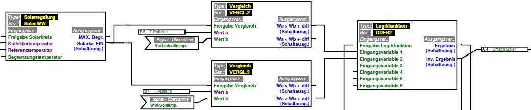
The Solar control SolarWW doesn't directly activate the solar thermal system. Instead it activates the two Comparison VERGL2 and VERGL3. VERGL2 checks if the bottom of the buffer (S 5) already is at temperature TVorlauf-FBH-Soll or higher. In this case the lower part of the buffer is completely filled with warm water for the floor heating system and the mode of operation may be switched back to tap water heating. VERGL3 checks if the temperature at the buffers top (S 7) already is at TWW-Soll, which is the target temperature for on-demand tap water heating. If this isn't the case, meaning that not enough warm water for tap water heating has been stored in the buffer, the inverted output switches the system into the tap water heating mode as well. The Logic function ODER2 combines both conditions for the operation in tap water heating mode and additionally sets valve A 4 which switches the feed line from the solar thermal system to a tap of the buffer positioned in the correct height not to disturb the temperature layers within the buffer.
Logic functions ODER1, ODER3 and ODER4 control the activation of the primary and secondary circuit of the solar thermal system:
- ODER1 combines the signals from the Solar control SolarWW and SolarHzg. If the UVR1611 controller activates one of the the whole solar thermal system is activated, i.e. primary and secondary circuit. The output of ODER1 acts upon the other function modules accordingly.
- ODER3 activates its output only if the solar thermal system is to work in floor heating mode. This is the case if either the Solar control SolarHzg is active or the Solar control SolarWW is active but the logic functions described above enforce a floor heating mode of operation.
- ODER4 activates the solar thermal system primary circuit by starting the solar collector pump. It is activated if either the solar thermal system as a whole gets activated by one of the two Solar controls or if the Start function or the Solar priority requests a flushing of the flat panel collector.
The buffer management implemented in this way is described by the following table. Here full and empty refer to the reference temperatures of the two Solar controls correspondingly:
| Buffer state | Solar power sufficient for | |
|---|---|---|
| floor heating mode | tap water heating mode | |
| Tap water zone empty Floor heating zone empty |
charge floor heating zone | charge tap water zone |
| Tap water zone full Floor heating zone empty |
charge floor heating zone | charge floor heating zone |
| Tap water zone empty Floor heating zone full |
buffer charging not possible | charge tap water zone |
| Tap water zone full Floor heating zone full |
buffer charging not possible | charge floor heating zone first then charge whole buffer(see following section) |
After the mode of operation has been selected dependent on available solar power and thermal energy already stored in the different zones of the buffer valve A4 is switched accordingly. In the next step the pump speed of the buffer charging pump A2 in the secondary circuit must be controlled so that the buffer is charged with the correct temperature. In contrast the collector pump A1 is operated at constant speed and transport the total collected solar thermal energy to the heat exchanger. Depending on the speed of the buffer charging pump A2 the temperature in the buffer feed line can be controlled seamless between the lowest temperature in the buffer (input of the buffer charging pump) and the maximum temperature delivered by the solar collector panel. The heat exchanger acts like a gear mechanism which translates the temperature present in the solar primary circuit into the temperature needed in the secondary circuit according to the current operating conditions.
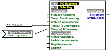
The control of the pump speed is accomplised with two PID controllers. Here controller SolarWW controls the pump speed in tap water heating mode and controller SolarHzg in floor heating mode:
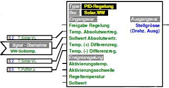
The PID controller SolarWW has both the absolute value control mode and the difference value control mode activated. Control variable in both cases is the temperature at the output line of the heat exchanger TSolar-VL which is fed via valve A4 into the buffer. For the absolute value control mode the target temperature of the tap water is used as the PID controller target value. For the difference value control mode the lower value of the target is set to the buffers bottom temperature and the difference is fixed to 3°C. Both PID controller modes work with a positive influence on the PID output so the pump speed will increase if the feed temperature rises above the target value. This increases the flow of water on the secondary side of the heat exchanger. The same thermal energy if transferred by the heat exchanger to a larger volume of water which causes the output temperature of the heat exchanger to drop thus closing the control loop.
If both the absolute value control mode and the difference value control mode are active on the PID controller its output will show the smaller of both values value. In tap water heating operation mode this results in the following control function:
- As long as the water for floor heating stored in the lower part of the buffer is cooler than the water in the upper part of the buffer the buffer gets charged from the top with the constant temperature required for on-demand tap water heating. This will store as much water with the corresponding temperature as possible.
- Over time tis water will form a zone with a temperature of tap water at the top of the buffer.
- Below this zone cooler water for floor heating is stored in the buffer. The boundary between the two zones will move top-down over time.
- If the zone boundary eventually reaches the bottom of the buffer the temperature at this position rises to the tap water temperature.
- Now the difference value mode of the PID controller becomes active and lowers the pump speed so that the feed temperature always is 3°C above the temperature at the bottom of the buffer.
- Because the feed line is connected to the top of the buffer the slightly elevated feed temperature also moves top-down through the buffer.
- If the elevated feed temperature reaches the bottom of the buffer the PID controller again will increase the feed temperature and the cycle starts from the beginning. In this way the whole buffer can be used to store thermal energy.
It is important to note that the temperature (S 5) at the bottom of the buffer must be selected as reference temperature for this to work. If the temperature at the top of the buffer would have been chosen instead a self-blocking effect would be the result. In this case the warm water fed into the buffer would collect at its top thus forming a pool of warm water there. The rising temperature in this zone would cause the feed temperature to rise as well. The maximum reachable temperature however is limited by the solar collectors temperature. This would make it increasingly difficult to reach the required feed temperature and would finally stop the solar thermal system even if storage capacity of the buffer remains unused.
In contrast the PID controller SolarHzg for the control of the feed temperature in floor heating mode works purely in difference control mode. Reference temperature here is the optimized floor heating support temperature THeizungsunterstützung, its calculation being described here. The feed line for this operation mode is directly connected to the middle of the buffer in order not to disturb the termal layers within the buffer. Here also the feed temperature isn't fixed to a constant value but will increase following a similar mechanism as described above. This will ensure that the maximal storage capacity of the buffer is used in this mode of operation also.
Finally the Analog function MAX(An)1 combines the pump speeds calculated by both PID controllers. The logic functions described above ensure that only one of the PID controllers is active at any point in time so the output signal from MAX(An)1 to the buffer charging pump A2 always is unambigous.